Search My Techie Guy

Tuesday, May 31, 2016

Housing Finance Bank (HFB) Uganda Introduces Mobile Banking

I have been HFB's client with a savings account for now 3 years, the biggest turn-off about their banking services was their ATM which is not VISA enabled. Meaning that it was likely for you to get stuck in a place that has no HFB ATM machine even if you have some money on your account. 
These guys were not even a member of the interswitch group ATMs.

Well the situation hasn't changed about the VISA ATM but i was impressed last week when i visited the bank and was introduced to their latest mobile banking service that makes everything flexible.
Meaning even if you were in a place that has no HFB ATM, you have an alternative of using their mobile banking service to transfer money either to another account or to your mobile money platform. 

Their mobile banking comes in two flavors:

1. The USS code *225#


2. The android App "HFB Mobile Banking App" 
     Am not sure if there is an equivalent for the iOS App


You will need to walk in and fill in some signup form to activate mobile banking for your account. After you have filled the form, you will receive an SMS with the USSD PIN and an activation key for the mobile App. The activation key for the mobile App expires if you don't activate it within 24 hours.

Wednesday, May 25, 2016

Troubleshooting kmd: IKE negotiation failed with error: No proposal chosen.

Summary (Message): 

> show log kmd-logs | match x.x.x.x
where x.x.x.x is the remote ike gateway IP address

kmd[1624]: IKE negotiation failed with error: No proposal chosen.

Problem or Goal:

Phase 2 of my IPsec tunnel was "DOWN", Phase 1 was "UP", tunnel interface was admin "UP" but protocol "DOWN"

Cause (Meaning):

The Junos device did not accept any of the IKE Phase 2 proposals that the specified IKE peer sent.

Solution (Action):

Verify the local Phase 2 VPN configuration elements.
The Phase 2 proposal elements include the following:


  • Authentication algorithm
  • Encryption algorithm
  • Lifetime kilobytes
  • Lifetime seconds
  • Protocol
  • Perfect Forward Secrecy


Either change the local configuration to accept at least one of the remote peer’s Phase 2 proposals, or contact the remote peer’s admin and arrange for the IKE configurations at both ends of the tunnel to use at least one mutually acceptable Phase 2 proposal.

References:

  1. How to analyze IKE Phase 2 VPN status messages


Problem Solved?

Thursday, May 19, 2016

How to capture tcp dump on juniper srx 5800 and analyze file using wireshark

Summary: 

How to take a tcp dump on Juniper SRX 5800. This tcp dump is of file type .pcap and can be analyzed using third party tools like wireshark.

Problem or Goal:

To analyze traffic traversing the firewall using wireshark

Cause:

For troubleshooting purposes

Solution:

Reference: How to create a PCAP packet capture on high-end SRX devices

Example:

Edit the config as below:

#set security datapath-debug capture-file my-capture
#set security datapath-debug capture-file format pcap
#set security datapath-debug capture-file size 1m
#set security datapath-debug capture-file files 5
#set security datapath-debug maximum-capture-size 1500
#set security datapath-debug action-profile do-capture event np-egress packet-dump
#set security datapath-debug action-profile do-capture event np-ingress packet-dump
#set security datapath-debug packet-filter my-filter action-profile do-capture
#set security datapath-debug packet-filter my-filter destination-prefix x.x.x.x/x
#commit 

To start the debug:

>request security datapath-debug capture start

To stop the debug:

>request security datapath-debug capture stop

You can use this command to show the captured packets, but the output doesn't make sense, you will have to export the file into third party tools like wireshark:

>show security datapath-debug capture

Before you pick the file to analyze it with wireshark, run this command:

>start shell user root
Password :
root% pwd
If you are not in /var/log;

root@% cd /var/log
root@% e2einfo -Ccapture -Snormalize -I my-capture -F my-capture.pcap

sucessfully convert 124 packets
root@% ls -ltr

You can use tools like WinSCP to copy the file from the SRX device to your computer.

When troubleshooting is finished, remove all datapath-debug configuration, including the datapath-debug configuration for packet capturing (packet-dump) which needs to be started/stopped manually. If any part of the debugging configuration remains active, it will continue using the resources of the device (CPU/memory).

#delete security datapath-debug
#commit

Problem Solved?

Yes.

Tuesday, May 17, 2016

Timeout occurred while processing the operation - Nokia Flexi Content Optimizer

Summary: 
"Timeout occurred while processing the operation. "

We have a Nokia Flexi Content Optimizer (FCO) solution in our network and we have been struggling with this error for quite some time now. when the FCO is inline, some websites return this error, however the websites are accessible with no errors when the FCO is removed from the path.

Problem or Goal:

Some websites are not accessible with the cache inline, and return this error "Timeout occurred while processing the operation. "

Cause:

The FCO experts say the issues is that the cache sends a SYNC packet to the webserver but never receives a response, hence returning that error code to client's browser.

See screen shot below of the error code:

HTTP Error 504 Gateway timeout
Solution:

unfortunately, we are still struggling with this issue.

Here are a few pointers:
HTTP Error 504 Gateway timeout

Problem Solved?

Not Yet, will update once done, but leave a comment if you can help out. will be glad

Monday, May 16, 2016

Announcement - Bank Scams and Tricksters

If you are using an internet banking system!!!
You might receive an SMS from a number
similar to the one that you get bank
notifications from. The SMS will indicate a
problem on your account and a 'consultant' will
contact you.
When the 'consultant' contacts you, he/she will
start confirming all your details and your
account number and will ask you what kind of a
phone you are using, etc… (please do not
release any details to them)
The fraudsters will then contact your mobile
phone service provider (which they already have
contacts within) and perform a SIM Swap.
The fraudster will then be able to receive OTP's
(One Time Pins) and/or RVN's (Random
Verification Numbers) from your bank and have
access to your bank accounts.
By the time you realize that your mobile number
is not working; Your money will be out of your
account.
Please broadcast and forward to others and let
everyone know about this very big scam going
on at the moment.

Share widely

Sunday, May 15, 2016

Integrated Routing and Bridging (IRB) on juniper router to achieve redundancy

Summary: 

Today i had a network scenario where two SBCs (Session Border Controllers) were supposed to connect to one router. The SBCs are from oracle and the router which is going to function as my border gateway router is a juniper MX5.

The SBCs are supposed to work in active/standby mode and are running VRRP between them selves. VRRP is Virtual Router Redundancy Protocol.
In this case the virtual IP will floating between the two SBCs depending on whichever is active.

Below is a summary of my setup:

Integrated Routing and Bridging
Problem or Goal:

From the router, we should be able to ping the active SBC, the virtual IP is always resident on the active SBC and we should be able to ping it from the router even if the SBCs switch positions.

Cause:

This is a common scenario, you find yourself in a situation where you have servers working in active/standby mode connected to one router yet you need to achieve redundancy. 

Solution:

For this to workout, the SBCs and the router interfaces need to be in one broadcast domain, so we are going to bridge the two router interfaces into one bridge domain using a technique called IRB (Integrated Routing and Bridging).

our IP plan is as below:

Network:   10.10.10.0/29           
Netmask:   255.255.255.248  
Wildcard:  0.0.0.7                      
Broadcast: 10.10.10.7            
HostMin:   10.10.10.1           
HostMax:   10.10.10.6            
Hosts/Net: 6   

The /29 gives us 6 IPs, 3 of the IPs will be used for the VRRP configuration on the SBCs, we shall need only one IP at the router side since we are using only one router. we shall use vlan 100 on both the router and the SBCs.

Below is the quick configuration:

set interfaces ge-1/0/0 description To_SBC01
set interfaces ge-1/1/0 description To_SBC02
set interfaces ge-1/0/0 vlan-tagging
set interfaces ge-1/1/0 vlan-tagging
set interfaces ge-1/0/0 unit 0 family bridge interface-mode trunk
set interfaces ge-1/1/0 unit 0 family bridge interface-mode trunk
set interfaces ge-1/0/0 unit 0 family bridge vlan-id-list 100
set interfaces ge-1/1/0 unit 0 family bridge vlan-id-list 100

set bridge-domains SBC domain-type bridge
set bridge-domains SBC vlan-id 100
set bridge-domains SBC routing-interface irb.100

set interfaces irb unit 100 description Connects_To_SBC
set interfaces irb unit 100 family inet address 10.10.10.4/29

Problem Solved?

Yes, from the router, am able to ping the virtual IP which is resident on whichever SBC is active. 

for any questions, please leave a comment

Saturday, May 14, 2016

Adding a Static IP route in a Windows Routing Table

Summary: 

This short post is to show you how to add a static IP route in a windows routing table.

Problem or Goal: 

Statically add an IP route in a windows routing table.

Cause: 

For my case, my laptop had two interfaces (The Local Area Connection on cable and the Wireless Network Connection), and i wanted to force traffic to a certain destination network out the LAN cable interface.

Solution: 

Statically define an IP route to your desired destination network and force it through the gateway that connects to the right interface.

Syntax:
route ADD xxx.xxx.xxx.xxx MASK xxx.xxx.xxx.xxx  xxx.xxx.xxx.xxx
Means:
route ADD “network” MASK “subnet mask”  “gateway ip”
Example:
route ADD 10.10.10.0 MASK 255.255.255.0 192.168.1.12
You can use this command to print the status of your routing table:
netstat -rn
Your routing table should now reflect that change, and all traffic to the 10.10.10.x network will now be sent through the interface that connects to the 192.168.1.12 gateway. 
The route add change will only stick across reboots if you add it with the -p flag, for example:
route -p ADD 10.10.10.0 MASK 255.255.255.0 192.168.1.12

Problem Solved?

YES

Friday, May 6, 2016

Quick creat a QR code for your website, facebook page or twitter page

I have just finished creating a QR code for my website URL at QR CODE GENERATOR
QRC stands for Quick Response Code.


Scans fine and you can even embed your website logo in the QR code if you choose to open a free account with them. I also like the fact that you can track the number of scans for your QR code.


Please install "BT Notice" app in remote device

Techie Jokes Nerd Jokes Techie Humor Comics Jokes

Just got a smart watch, I think it's the "China" type because I can't seem to establish the brand. When I try to launch the camera, it gives me that error message "please install BT Notice app in remote device". Am yet to find an app that works with this watch. If you know any please reply via the comments section below.

I think i have figured it out:

1. Go to menu on the smart watch
2. Select "Settings"
3. Select "APK"
4. Select "SWatch (Google)"
5. A QR code will be displayed on your smart watch, scan this QR code using a QR scanner on your phone (You will have to  first install a "QRC" Quick Response Code scanner on your phone).
6. The QRC scan will display a link to Google Play store where you will download the App. Open that link.
7. The Link will open in Google Play Store; The App is called "SmileNotification" by smilemi, install the App.

I have tested it on my phone, yes it can launch the camera and take the picture although it's not saving the pictures in my phone gallery!

Thursday, May 5, 2016

Stacking EX4200-24F with EX4200-24T using virtual chassis and vc ports

Summary: 

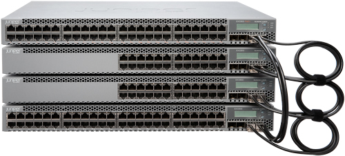
Stacking EX4200-24F with EX4200-24T using virtual chassis and vc ports.

Disclaimer: 
This article is not a subsitute to the original juniper documentation, i recommend you read the original juniper manuals as they keep track of all the software changes.

References:

Problem or Goal:

To increase port count on your current switch

Cause:

Solution:

1. Gather the serial numbers for the two switches:
> show chassis hardware

2. Set the Virtual Chassis mode to mixed:
This is good if in future you wish to add mixed members to the EX4200 VC, say if you add an EX4500, run the command below on both switches.
> request virtual-chassis mode mixed

3. Reboot both switches for the command in (2) above to take effect:
> request system reboot

4. when you have finished rebooting both switches, leave the switch that is supposed to be master powered on and power off the switch that is supposed to be backup. It's time to do the "preprovisioned configuration" on the master switch.

5. Specify the preprovisioned configuration mode:
[edit virtual-chassis]
# set preprovisioned

6. Specify all the members that will be included in the Virtual Chassis configuration, listing each switch's serial number with the desired member ID and the desired role:
[edit virtual-chassis]

# set member 0 serial-number XX0213517333 role routing-engine
# set member 1 serial-number XX0213517332 role routing-engine

7. (Optional. Recommended for a two-member Virtual Chassis) Disable the split and merge feature:
[edit virtual-chassis]
# set no-split-detection

8. Check you configuration so far:
# commit check

9. Commit your configuration on the master
# commit

10. Connect the two switches using a VC cable connected to the vc-ports

11. Power on the second switch (the backup member)

12. When the second switch has fully booted, it will automatically be added to the virtual chassis as a back up; here are some helpful show commands to verify that your VC is successful.

# show virtual-chassis vc-port 
# show virtual-chassis
# show chassis hardware

Problem Solved? 

YES

Stacking juniper ex4500 with ex4550 switches using virtual chassis and vc-ports

Summary: 

I have just finished stacking juniper switches and for this particular work, i stacked a mixture of EX4550-32F and EX4500-40F. everything was smooth for me i should say and i got it right at first attempt. below i share my experience.

Disclaimer: This blog post is not a substitute for the original juniper documents and manuals, as a matter of fact, my only reference was juniper materials when i was setting this up:

Link1: configuring mixed virtual chassis
Link2: understanding EX Series VC components
Link3: VC cabling examples

Problem or Goal:

i had run out of port count and i need more port for new projects.

Cause:

Running out of port count

Solution:

For my case, the old switch was the EX4500-40F and was carrying live traffic and it's the switch i wanted to be the master. Here is the simple procedure i followed without having to restart my old switch. we are going to use the preprovisioned configuration mode:

1. Gather the serial numbers for the two switches:
> show chassis hardware

2. (On the EX4500-40F, that is going to be the master) Verify the PIC mode setting:
> show chassis pic-mode

3. If the PIC mode setting is not set to virtual-chassis, set the PIC mode to virtual-chassis:
> request chassis pic-mode virtual-chassis

4. If the PIC mode in step (3) above was changed, you will have to reboot your switch. for my case it was already set to "virtual-chassis" to i got away with having to reboot my core switch and interrupting service.

> request system reboot

> show chassis pic-mode     
fpc0:
------------------------------------------------------------------
    Pic Mode: PIC 3: virtual-chassis

5. At this point, the switch that is supposed to be the master (EX4500-40F) is powered up whereas the new switch (backup) is powered off (EX4550-32F). It's time to do the "preprovisioned configuration" on the master switch (EX4500-40F)

6. Specify the preprovisioned configuration mode:
[edit virtual-chassis]
# set preprovisioned

7. Specify all the members that will be included in the Virtual Chassis configuration, listing each switch's serial number with the desired member ID and the desired role:
[edit virtual-chassis]

# set member 0 serial-number BR0213517499 role routing-engine
# set member 1 serial-number BR0213517498 role routing-engine

8. (Optional. Recommended for a two-member Virtual Chassis) Disable the split and merge feature:
[edit virtual-chassis]
# set no-split-detection

9. Check you configuration so far:
# commit check

10. Commit your configuration on the master
# commit

11. Connect the VC cable to the VC-Ports, for my case i connected vcp-0 of EX4500-40F to vcp-0 of EX4550-32F, there are located at the back panel.


11. Power on the new switch (EX4550-32F)

12. EX4550-32F booted and was automatically added to the virtual chassis as a back up; here are some helpful show commands to verify that your VC is successful.

# show virtual-chassis vc-port 
# show virtual-chassis
# show chassis hardware

Problem Solved?

Absolutely, i now have 32 more ports for my new projects.

For any questions regarding this project, use the comment section. cheers

Tuesday, May 3, 2016

mount_msdosfs: /dev/da1s1: No such file or directory when trying to mount a flash to juniper ex series switch

Summary: 

When trying to mount a flash disk to a juniper switch, i got this error "mount_msdosfs: /dev/da1s1: No such file or directory"

Problem or Goal:

root@:RE:0% mkdir /var/tmp/usb
root@:RE:0% mount_msdosfs /dev/da1s1 /var/tmp/usb
mount_msdosfs: /dev/da1s1: No such file or directory

on the console, when i insert the flash drive, i observe these errors:

root@:RE:0% umass1: Alcor Micro Mass Storage Device, rev 2.00/0.01, addr 4
da1 at umass-sim1 bus 1 target 0 lun 0
da1: <Generic USB Flash Disk 7.76> Removable Direct Access SCSI-4 device 
da1: 40.000MB/s transfers
da1: Attempt to query device size failed: NOT READY, Medium not present
(da1:umass-sim1:1:0:0): READ CAPACITY. CDB: 25 0 0 0 0 0 0 0 0 0 
(da1:umass-sim1:1:0:0): CAM Status: SCSI Status Error
(da1:umass-sim1:1:0:0): SCSI Status: Check Condition
(da1:umass-sim1:1:0:0): NOT READY asc:3a,0
(da1:umass-sim1:1:0:0): Medium not present
(da1:umass-sim1:1:0:0): Unretryable error
Opened disk da1 -> 6

Cause:

Most probably, the flash disk is not well formatted.

Solution: 

I took out the flash drive from the switch and formatted it on a windows PC using file system FAT

Problem Solved?

Yes, after i inserted it back in the switch and i was able to mount it.

root@:RE:0% umass1: Generic Mass Storage, rev 2.00/1.06, addr 4
da1 at umass-sim1 bus 1 target 0 lun 0
da1: <Generic Flash Disk 8.07> Removable Direct Access SCSI-4 device 
da1: 40.000MB/s transfers
da1: 7800MB (15974400 512 byte sectors: 255H 63S/T 994C)

root@:RE:0% mount_msdosfs /dev/da1s1 /var/tmp/usb
root@:RE:0% ls -ltr /var/tmp/usb/
total 219776
-rwxr-xr-x  1 root  field  112517772 May  2  2016 jinstall-ex-4500-12.3R12.4-domestic-signed.tgz

How to mount USB flash drive on Juniper EX series switches

Summary:

Am trying to upgrade my juniper EX4200 from JUNOS Base OS Software Suite [12.3R9.4] to 12.3R12.4 in preparation for virtual chassis, Juniper recommends that all switches within the same virtual chassis run the same software version. And because my VC will be a mixture of EX4550/EX4500/EX4200, juniper recommended that i use 12.3R12.4

So i have my software already downloaded and on a flash disk

Problem or Goal:

I need to transfer the software to the switches using a flash drive

Cause:

You probably have no network connectivity to the switches to do an FTP transfer, or you are working on a new switch.

Solution: 

1. Enter the shell as root:

root> start shell user root
root@:RE:0%

2. Before inserting the USB device, perform the following:

root@:RE:0% ls /dev/da*
/dev/da0        /dev/da0s1c     /dev/da0s2c     /dev/da0s3d     /dev/da0s4c
/dev/da0s1      /dev/da0s2      /dev/da0s3      /dev/da0s3e     /dev/da0s4d
/dev/da0s1a     /dev/da0s2a     /dev/da0s3c     /dev/da0s4

3. Insert the USB drive in the USB port. The following output will be displayed:

root@:RE:0% umass1: Generic Mass Storage, rev 2.00/1.06, addr 3
da1 at umass-sim1 bus 1 target 0 lun 0
da1: <Generic Flash Disk 8.07> Removable Direct Access SCSI-4 device
da1: 40.000MB/s transfers
da1: 7800MB (15974400 512 byte sectors: 255H 63S/T 994C)

root@:RE:0% ls /dev/da*
/dev/da0        /dev/da0s2      /dev/da0s3c     /dev/da0s4c
/dev/da0s1      /dev/da0s2a     /dev/da0s3d     /dev/da0s4d
/dev/da0s1a     /dev/da0s2c     /dev/da0s3e     /dev/da1
/dev/da0s1c     /dev/da0s3      /dev/da0s4      /dev/da1s1

Note: if you compare the "ls /dev/da*" output before inserting the flash drive and after inserting the drive, you will notice these have been added:

/dev/da1 and "/dev/da1s1"

Your USB drive is located here "/dev/da1s1"

4. Create a directory for the USB drive to mount to:

root@:RE:0% mkdir /var/tmp/usb

5. Mount the USB drive to the /var/tmp/usb directory:

root@:RE:0% mount_msdosfs /dev/da1s1 /var/tmp/usb

root@:RE:0% ls /var/tmp/usb
jinstall-ex-4200-12.3R12.4-domestic-signed.tgz
jinstall-ex-4500-12.3R12.4-domestic-signed.tgz

Problem Solved?

Yes 

6. You can now copy any of the USB files to the /var/tmp directory on the switch:

root@:RE:0% cp /var/tmp/usb/jinstall-ex-4200-12.3R12.4-domestic-signed.tgz /var/tmp

7. Now unmount the USB drive after the file is completely copied:

root@:RE:0% umount /var/tmp/usb

References: juniper.net

Monday, May 2, 2016

DRUPAL WEBSITE PERMISSIONS FIX

Summary: 
DRUPAL WEBSITE PERMISSIONS FIX (UNIX/LINUX)

Problem or Goal:
Recommended steps to fix the website file/folder permissions

Cause: 
File Permission issues on drupal

Solution: 

# 1. Create a new example user.

useradd -s /bin/bash -m example;

# 2. Now add that user to the Apache group. On Ubuntu/Debian this group is usually
# called www-data, on CentOS it's usually apache.

usermod -a -G www-data example;

# 3. Set up a password for this user.
  
passwd example;

# 4. Now set the group to the Apache group. -R means recursive, and -v means 
# verbose mode.

chgrp -Rv www-data sites/default/files

# 5. Next we'll set up permissions so that the web server can always write to any 
# file that is in this directory. We do this by using 2775 in our chmod command. 
# The 2 means that the group id will be preserved for any new files created in this 
# directory. What that means is that www--data will always be the group on any files, 
# thereby ensuring that web server and the user will both always have write 
# permissions to any new files that are placed in this directory. 

chmod 2775 sites/default/files

# 6. If there are any existing files in this directory, be sure the web server has 
# write perms on them.

chmod g+w -R sites/default/files

# 7. Ensure that all users only have read permissions.

chmod 444 sites/default/settings.php

# ------------------------------------------------------

Problem Solved?

Yes, Comment if there are any questions.