Summary:
Today i found myself in a situation where i have to add some juniper switches (EX4200s and EX4500s) to our TACACs+ server, for the switches where the remote access IP was configured on the management interface (me0) or any other interface but accessible from the global routing table (inet.0) i didn't face any issues.
However, for switches were the operation and maintenance IP was configured within a routing instance, i had issues because there is no routing-instance specific configuration for TACACs+
TACACs+ server has to be reachable from the global routing table.
Problem or Goal:
Configuring TACACs on a switch with routing instances and VRFs
Cause:
TACACs+ server has to be reachable from the global routing table.
Solution:
Instead of using vlan routed interfaces or the normal interfaces bound to a routing instance, use the management interface (me0).
Juniper has an interface dedicated for management that uses the control plane and is useful for out-of-band management.
Example:
If you have virtual chassis enabled:
set interfaces vme unit 0 family inet address 10.172.2.2/24
if you are working on a single switch without virtual chassis:
set interfaces me0 unit 0 family inet address 10.172.2.2/24
You will need to connect the MGT interfaces to your LAN network.
You also need to add this part of configuration on the switch according to your TACACs server details:
set system login user remote full-name "Tacacs+ System User"
set system login user remote uid xxxx
set system login user remote class super-user
set system authentication-order tacplus
set system authentication-order password
set system tacplus-server 10.0.X.X port 49
set system tacplus-server 10.0.X.X secret tacacs_secret_key
set system tacplus-server 10.0.X.X single-connection
set system tacplus-server 10.0.X.X source-address 10.172.2.2
set system accounting events [ change-log interactive-commands login ] destination tacplus server 10.0.X.X
Don't forget to create a failover local login incase TACACs+ is offline:
set system login user admin uid xxxx
set system login user admin class super-user
set system login user admin authentication plain-text-password
Problem Solved?
Yes

Showing posts with label juniper. Show all posts
Showing posts with label juniper. Show all posts
Wednesday, October 12, 2016


Friday, August 12, 2016
Installing Tacacs plus to manage juniper routers, switches and firewalls
Summary:
Today am tasked with installing tacacs+ to manage authentication to all the IP nodes, most of the nodes here are juniper. sorry i won't be very organized in writing this article, i will pretty much paste every challenge and solution as i work, in fact this will be my new style of work instead of waiting to first finish the work and then putting in more time to write a clean article. let's face it, i suck at writing and am lazy just like all other engineers :-), so sorry if this article is a mess.
Problem or Goal:
To install TACACS+ to manage authentication to juniper nodes (routers, switches, firewalls)
Cause:
Consider this a good house keeping cause, you need centralized management of logins, logging, easy to manage users and an added layer of security.
Solution:
Working on setting up the server side
1. Platform
# cat /etc/*release
openSUSE 13.2 (x86_64)
VERSION = 13.2
2. Download site for TACACS+ rpm
3. ftp/sftp the above file to your server; you can use FileZilla or WinSCP
4. Install using Zypper (but oops, looks like i have some missing dependencies!!! welcome to the opensource world :-) )
# zypper --non-interactive install tac_plus-4.0.4.26-1.52.x86_64.rpm
Loading repository data...
Reading installed packages...
Resolving package dependencies...
Problem: nothing provides libtacacs.so.1()(64bit) needed by tac_plus-4.0.4.26-1.52.x86_64
Solution 1: do not install tac_plus-4.0.4.26-1.52.x86_64
Solution 2: break tac_plus-4.0.4.26-1.52.x86_64 by ignoring some of its dependencies
5. Download site for libtacacs
libtacacs1 rpm build for : OpenSuSE. For other distributions click libtacacs1.
Problem Solved?
Today am tasked with installing tacacs+ to manage authentication to all the IP nodes, most of the nodes here are juniper. sorry i won't be very organized in writing this article, i will pretty much paste every challenge and solution as i work, in fact this will be my new style of work instead of waiting to first finish the work and then putting in more time to write a clean article. let's face it, i suck at writing and am lazy just like all other engineers :-), so sorry if this article is a mess.
Problem or Goal:
To install TACACS+ to manage authentication to juniper nodes (routers, switches, firewalls)
Cause:
Consider this a good house keeping cause, you need centralized management of logins, logging, easy to manage users and an added layer of security.
Solution:
Working on setting up the server side
1. Platform
# cat /etc/*release
openSUSE 13.2 (x86_64)
VERSION = 13.2
2. Download site for TACACS+ rpm
3. ftp/sftp the above file to your server; you can use FileZilla or WinSCP
4. Install using Zypper (but oops, looks like i have some missing dependencies!!! welcome to the opensource world :-) )
# zypper --non-interactive install tac_plus-4.0.4.26-1.52.x86_64.rpm
Loading repository data...
Reading installed packages...
Resolving package dependencies...
Problem: nothing provides libtacacs.so.1()(64bit) needed by tac_plus-4.0.4.26-1.52.x86_64
Solution 1: do not install tac_plus-4.0.4.26-1.52.x86_64
Solution 2: break tac_plus-4.0.4.26-1.52.x86_64 by ignoring some of its dependencies
5. Download site for libtacacs
libtacacs1 rpm build for : OpenSuSE. For other distributions click libtacacs1.
| Name : libtacacs1 | |
| Version : 4.0.4.26 | Vendor : obs://build_opensuse_org/home:anubisg1 |
| Release : 1.52 | Date : 2013-08-24 07:40:02 |
| Group : Development/Languages/C and C++ | Source RPM : tac_plus-4.0.4.26-1.52.src.rpm |
| Size : 0.35 MB | |
| Packager : (none) | |
| Summary : Tacacs+ library | |
| Description : This package contains TACACS+ library | |
RPM found in directory: /mirror/ftp5.gwdg.de/pub/opensuse/repositories/home:/anubisg1:/networking/openSUSE_Factory/x86_64 | |
Download
|
6. Similarly download and ftp this package to your server
7. Install the libtacacs rpm as below:
# zypper --non-interactive install libtacacs1-4.0.4.26-1.52.x86_64.rpm
Loading repository data...
Reading installed packages...
Resolving package dependencies...
The following NEW package is going to be installed:
libtacacs1
1 new package to install.
Overall download size: 24.1 KiB. Already cached: 0 B After the operation, additional 354.6 KiB will be used.
Continue? [y/n/? shows all options] (y): y
Retrieving package libtacacs1-4.0.4.26-1.52.x86_64 (1/1), 24.1 KiB (354.6 KiB unpacked)
Checking for file conflicts: ..............................................................................................................................................................................[done]
(1/1) Installing: libtacacs1-4.0.4.26-1.52 ................................................................................................................................................................[done]
Additional rpm output:
warning: /var/cache/zypp/packages/_tmpRPMcache_/libtacacs1-4.0.4.26-1.52.x86_64.rpm: Header V3 DSA/SHA1 Signature, key ID e558cb38: NOKEY
8. Now re-attempt to the tac_plus installation, this time it should be successful after adding the libtacacs dependency
# zypper --non-interactive install tac_plus-4.0.4.26-1.52.x86_64.rpm
Loading repository data...
Reading installed packages...
Resolving package dependencies...
The following NEW package is going to be installed:
tac_plus
1 new package to install.
Overall download size: 95.1 KiB. Already cached: 0 B After the operation, additional 229.0 KiB will be used.
Continue? [y/n/? shows all options] (y): y
Retrieving package tac_plus-4.0.4.26-1.52.x86_64 (1/1), 95.1 KiB (229.0 KiB unpacked)
Checking for file conflicts: ..............................................................................................................................................................................[done]
(1/1) Installing: tac_plus-4.0.4.26-1.52 ..................................................................................................................................................................[done]
Additional rpm output:
warning: /var/cache/zypp/packages/_tmpRPMcache_/tac_plus-4.0.4.26-1.52.x86_64.rpm: Header V3 DSA/SHA1 Signature, key ID e558cb38: NOKEY
9. Test your installation, looks good :-)
# tac_plus -v
tac_plus version F4.0.4.26
ACLS
FIONBIO
LIBWRAP
LINUX
LITTLE_ENDIAN
LOG_DAEMON
PAM
NO_PWAGE
REAPCHILD
RETSIGTYPE RETSIGTYPE
SHADOW_PASSWORDS
SIGTSTP
SIGTTIN
SIGTTOU
SO_REUSEADDR
STRERROR
TAC_PLUS_PORT
UENABLE
__STDC__
10. Tacacs config file is located at:
/etc/tac_plus.conf
11. Tacacs manual is located at:
# man tac_plus
12. The tacacs plus daemon is found at:
# /etc/init.d/tac_plus
Usage: tacacs {start|stop|status|restart|reload}
13. Starting tacacs (oops looks like we have an error! )
SMPP:/etc/init.d # ./tac_plus start
./tac_plus: line 16: /etc/rc.d/init.d/functions: No such file or directory
./tac_plus: line 19: .: /etc/sysconfig/network: is a directory
./tac_plus: line 22: [: =: unary operator expected
Starting tacacs+: ./tac_plus: line 35: daemon: command not found
14. Edit the tacacs plus init file to comment out the above lines and also delete the "daemon" command
# vi /etc/init.d/tac_plus
# Source function library.
#. /etc/rc.d/init.d/functions
# Source networking configuration.
#. /etc/sysconfig/network
start)
# Start daemons.
echo -n "Starting tacacs+: "
/usr/bin/tac_plus -C $CONFIG ${LOGFILE:+-l $LOGFILE} ${WHOLOG:+-w $WHOLOG} ${DEBUG_LEVEL:+-d $DEBUG_LEVEL}
RETVAL=$?
echo
[ $RETVAL == 0 ] && touch /var/lock/subsys/tac_plus
;;
15. Attempt to start tacacs again:
SMPP:/etc/init.d # /etc/init.d/tac_plus start
Starting tacacs+:
16. check to make sure it's running in the processes
SMPP:/etc/init.d # ps -ef | grep tac
root 20176 1 0 20:26 pts/0 00:00:00 /usr/bin/tac_plus -C /etc/tac_plus.conf
Problem Solved?
Friday, June 17, 2016
How to configure port mirroring on juniper MX series routers?
Summary:
How to configure port mirroring on juniper MX series routers?
Problem or Goal:
You are in a situation where you want to capture and analyse live traffic in/out of a juniper MX series router interface. The most common network analyzer tool is wireshark.
Cause:
There are so many scenarios why you might want to capture and analyze network traffic at protocol level, in many cases you would be troubleshooting an application or network problem.
Solution:
In this example, a laptop with a network analyzer tool (Wireshark) is connected to port ge-1/1/2 of the router.
The traffic of interest is in/out of interfaces ge-1/1/0 and ge-1/1/1, i.e. from the clients laptops towards the webserver, two-way.
1. Configure the interface where you are going to connect the wireshark laptop
set interface ge-1/1/2 description to_wireshark_laptop
set interface ge-1/1/2 unit 0 family inet address 192.168.0.1/30
set interfaces ge-1/1/2 unit 0 family inet address 192.168.0.1/30 arp 192.168.0.2 mac A0:1D:48:B3:A1:26
2. Create the filter for example this filter is called "wireshark_capture"
set firewall filter wireshark_capture term 1 from source-address 0.0.0.0/0
set firewall filter wireshark_capture term 1 from destination-address 0.0.0.0/0
set firewall filter wireshark_capture term 1 then port-mirror
set firewall filter wireshark_capture term 1 then count output-pm
set firewall filter wireshark_capture term 1 then accept
set firewall filter wireshark_capture term allow-all-else then accept
3. Apply the filter to the interfaces carrying the traffic of interest
set interfaces ge-1/1/0 unit 0 family inet filter output wireshark_capture
set interfaces ge-1/1/0 unit 0 family inet filter input wireshark_capture
set interfaces ge-1/1/1 unit 0 family inet filter output wireshark_capture
set interfaces ge-1/1/1 unit 0 family inet filter input wireshark_capture
4. Configure the port mirror
set forwarding-options port-mirroring input rate 1
set forwarding-options port-mirroring input run-length 1
set forwarding-options port-mirroring family inet output interface ge-1/1/2.0 next-hop 192.168.0.2
set forwarding-options port-mirroring family inet output no-filter-check
5. Commit the configuration
#commit check
#commit
How to configure port mirroring on juniper MX series routers?
Problem or Goal:
You are in a situation where you want to capture and analyse live traffic in/out of a juniper MX series router interface. The most common network analyzer tool is wireshark.
Cause:
There are so many scenarios why you might want to capture and analyze network traffic at protocol level, in many cases you would be troubleshooting an application or network problem.
Solution:
In this example, a laptop with a network analyzer tool (Wireshark) is connected to port ge-1/1/2 of the router.
The traffic of interest is in/out of interfaces ge-1/1/0 and ge-1/1/1, i.e. from the clients laptops towards the webserver, two-way.
 |
| Port Mirroring on Juniper MX series routers |
set interface ge-1/1/2 description to_wireshark_laptop
set interface ge-1/1/2 unit 0 family inet address 192.168.0.1/30
set interfaces ge-1/1/2 unit 0 family inet address 192.168.0.1/30 arp 192.168.0.2 mac A0:1D:48:B3:A1:26
set firewall filter wireshark_capture term 1 from source-address 0.0.0.0/0
set firewall filter wireshark_capture term 1 from destination-address 0.0.0.0/0
set firewall filter wireshark_capture term 1 then port-mirror
set firewall filter wireshark_capture term 1 then count output-pm
set firewall filter wireshark_capture term 1 then accept
set firewall filter wireshark_capture term allow-all-else then accept
3. Apply the filter to the interfaces carrying the traffic of interest
set interfaces ge-1/1/0 unit 0 family inet filter output wireshark_capture
set interfaces ge-1/1/0 unit 0 family inet filter input wireshark_capture
set interfaces ge-1/1/1 unit 0 family inet filter output wireshark_capture
set interfaces ge-1/1/1 unit 0 family inet filter input wireshark_capture
4. Configure the port mirror
set forwarding-options port-mirroring input rate 1
set forwarding-options port-mirroring input run-length 1
set forwarding-options port-mirroring family inet output interface ge-1/1/2.0 next-hop 192.168.0.2
set forwarding-options port-mirroring family inet output no-filter-check
#commit check
#commit
Wednesday, May 25, 2016
Troubleshooting kmd: IKE negotiation failed with error: No proposal chosen.
Summary (Message):
> show log kmd-logs | match x.x.x.x
where x.x.x.x is the remote ike gateway IP address
kmd[1624]: IKE negotiation failed with error: No proposal chosen.
Problem or Goal:
Phase 2 of my IPsec tunnel was "DOWN", Phase 1 was "UP", tunnel interface was admin "UP" but protocol "DOWN"
Cause (Meaning):
The Junos device did not accept any of the IKE Phase 2 proposals that the specified IKE peer sent.
Solution (Action):
Verify the local Phase 2 VPN configuration elements.
The Phase 2 proposal elements include the following:
Either change the local configuration to accept at least one of the remote peer’s Phase 2 proposals, or contact the remote peer’s admin and arrange for the IKE configurations at both ends of the tunnel to use at least one mutually acceptable Phase 2 proposal.
References:
Problem Solved?
> show log kmd-logs | match x.x.x.x
where x.x.x.x is the remote ike gateway IP address
kmd[1624]: IKE negotiation failed with error: No proposal chosen.
Problem or Goal:
Phase 2 of my IPsec tunnel was "DOWN", Phase 1 was "UP", tunnel interface was admin "UP" but protocol "DOWN"
Cause (Meaning):
The Junos device did not accept any of the IKE Phase 2 proposals that the specified IKE peer sent.
Solution (Action):
Verify the local Phase 2 VPN configuration elements.
The Phase 2 proposal elements include the following:
- Authentication algorithm
- Encryption algorithm
- Lifetime kilobytes
- Lifetime seconds
- Protocol
- Perfect Forward Secrecy
Either change the local configuration to accept at least one of the remote peer’s Phase 2 proposals, or contact the remote peer’s admin and arrange for the IKE configurations at both ends of the tunnel to use at least one mutually acceptable Phase 2 proposal.
References:
Problem Solved?
Sunday, May 15, 2016
Integrated Routing and Bridging (IRB) on juniper router to achieve redundancy
Summary:
Today i had a network scenario where two SBCs (Session Border Controllers) were supposed to connect to one router. The SBCs are from oracle and the router which is going to function as my border gateway router is a juniper MX5.
The SBCs are supposed to work in active/standby mode and are running VRRP between them selves. VRRP is Virtual Router Redundancy Protocol.
In this case the virtual IP will floating between the two SBCs depending on whichever is active.
Below is a summary of my setup:
Problem or Goal:
From the router, we should be able to ping the active SBC, the virtual IP is always resident on the active SBC and we should be able to ping it from the router even if the SBCs switch positions.
Cause:
This is a common scenario, you find yourself in a situation where you have servers working in active/standby mode connected to one router yet you need to achieve redundancy.
Solution:
For this to workout, the SBCs and the router interfaces need to be in one broadcast domain, so we are going to bridge the two router interfaces into one bridge domain using a technique called IRB (Integrated Routing and Bridging).
our IP plan is as below:
Network: 10.10.10.0/29
Netmask: 255.255.255.248
Wildcard: 0.0.0.7
Broadcast: 10.10.10.7
HostMin: 10.10.10.1
HostMax: 10.10.10.6
Hosts/Net: 6
The /29 gives us 6 IPs, 3 of the IPs will be used for the VRRP configuration on the SBCs, we shall need only one IP at the router side since we are using only one router. we shall use vlan 100 on both the router and the SBCs.
Below is the quick configuration:
set interfaces ge-1/0/0 description To_SBC01
set interfaces ge-1/1/0 description To_SBC02
set interfaces ge-1/0/0 vlan-tagging
set interfaces ge-1/1/0 vlan-tagging
set interfaces ge-1/0/0 unit 0 family bridge interface-mode trunk
set interfaces ge-1/1/0 unit 0 family bridge interface-mode trunk
set interfaces ge-1/0/0 unit 0 family bridge vlan-id-list 100
set interfaces ge-1/1/0 unit 0 family bridge vlan-id-list 100
set bridge-domains SBC domain-type bridge
set bridge-domains SBC vlan-id 100
set bridge-domains SBC routing-interface irb.100
set interfaces irb unit 100 description Connects_To_SBC
set interfaces irb unit 100 family inet address 10.10.10.4/29
Problem Solved?
Yes, from the router, am able to ping the virtual IP which is resident on whichever SBC is active.
for any questions, please leave a comment
Today i had a network scenario where two SBCs (Session Border Controllers) were supposed to connect to one router. The SBCs are from oracle and the router which is going to function as my border gateway router is a juniper MX5.
The SBCs are supposed to work in active/standby mode and are running VRRP between them selves. VRRP is Virtual Router Redundancy Protocol.
In this case the virtual IP will floating between the two SBCs depending on whichever is active.
Below is a summary of my setup:
 |
| Integrated Routing and Bridging |
From the router, we should be able to ping the active SBC, the virtual IP is always resident on the active SBC and we should be able to ping it from the router even if the SBCs switch positions.
Cause:
This is a common scenario, you find yourself in a situation where you have servers working in active/standby mode connected to one router yet you need to achieve redundancy.
Solution:
For this to workout, the SBCs and the router interfaces need to be in one broadcast domain, so we are going to bridge the two router interfaces into one bridge domain using a technique called IRB (Integrated Routing and Bridging).
our IP plan is as below:
Network: 10.10.10.0/29
Netmask: 255.255.255.248
Wildcard: 0.0.0.7
Broadcast: 10.10.10.7
HostMin: 10.10.10.1
HostMax: 10.10.10.6
Hosts/Net: 6
The /29 gives us 6 IPs, 3 of the IPs will be used for the VRRP configuration on the SBCs, we shall need only one IP at the router side since we are using only one router. we shall use vlan 100 on both the router and the SBCs.
Below is the quick configuration:
set interfaces ge-1/0/0 description To_SBC01
set interfaces ge-1/1/0 description To_SBC02
set interfaces ge-1/0/0 vlan-tagging
set interfaces ge-1/1/0 vlan-tagging
set interfaces ge-1/0/0 unit 0 family bridge interface-mode trunk
set interfaces ge-1/1/0 unit 0 family bridge interface-mode trunk
set interfaces ge-1/0/0 unit 0 family bridge vlan-id-list 100
set interfaces ge-1/1/0 unit 0 family bridge vlan-id-list 100
set bridge-domains SBC domain-type bridge
set bridge-domains SBC vlan-id 100
set bridge-domains SBC routing-interface irb.100
set interfaces irb unit 100 description Connects_To_SBC
set interfaces irb unit 100 family inet address 10.10.10.4/29
Problem Solved?
Yes, from the router, am able to ping the virtual IP which is resident on whichever SBC is active.
for any questions, please leave a comment
Thursday, May 5, 2016
Stacking EX4200-24F with EX4200-24T using virtual chassis and vc ports
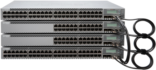
Stacking EX4200-24F with EX4200-24T using virtual chassis and vc ports.
Disclaimer: This article is not a subsitute to the original juniper documentation, i recommend you read the original juniper manuals as they keep track of all the software changes.
References:
Problem or Goal:
To increase port count on your current switch
Cause:
Solution:
1. Gather the serial numbers for the two switches:
> show chassis hardware
2. Set the Virtual Chassis mode to mixed:
This is good if in future you wish to add mixed members to
the EX4200 VC, say if you add an EX4500, run the command below
on both switches.
> request virtual-chassis mode mixed
3. Reboot both switches for the command in (2) above to take effect:
> request system reboot
4. when you have finished rebooting both switches, leave the switch that is supposed to be master powered on and power off the switch that is supposed to be backup. It's time to do the "preprovisioned configuration" on the master switch.
5. Specify the preprovisioned configuration mode:
[edit virtual-chassis]
# set preprovisioned
6. Specify all the members that will be included in the Virtual Chassis configuration, listing each switch's serial number with the desired member ID and the desired role:
[edit virtual-chassis]
# set member 0 serial-number XX0213517333 role routing-engine
# set member 1 serial-number
XX0213517332 role routing-engine
7. (Optional. Recommended for a two-member Virtual Chassis) Disable the split and merge feature:
[edit virtual-chassis]
# set no-split-detection
8. Check you configuration so far:
# commit check
9. Commit your configuration on the master
# commit
10. Connect the two switches using a VC cable connected to the vc-ports
11. Power on the second switch (the backup member)
12. When the second switch has fully booted, it will automatically be added to the virtual chassis as a back up; here are some helpful show commands to verify that your VC is successful.
# show virtual-chassis vc-port
# show virtual-chassis
# show chassis hardware
Problem Solved?
YES
Stacking juniper ex4500 with ex4550 switches using virtual chassis and vc-ports
Summary:
I have just finished stacking juniper switches and for this particular work, i stacked a mixture of EX4550-32F and EX4500-40F. everything was smooth for me i should say and i got it right at first attempt. below i share my experience.
Disclaimer: This blog post is not a substitute for the original juniper documents and manuals, as a matter of fact, my only reference was juniper materials when i was setting this up:
Link1: configuring mixed virtual chassis
Link2: understanding EX Series VC components
Link3: VC cabling examples
Problem or Goal:
i had run out of port count and i need more port for new projects.
Cause:
Running out of port count
Solution:
For my case, the old switch was the EX4500-40F and was carrying live traffic and it's the switch i wanted to be the master. Here is the simple procedure i followed without having to restart my old switch. we are going to use the preprovisioned configuration mode:
1. Gather the serial numbers for the two switches:
> show chassis hardware
2. (On the EX4500-40F, that is going to be the master) Verify the PIC mode setting:
> show chassis pic-mode
3. If the PIC mode setting is not set to virtual-chassis, set the PIC mode to virtual-chassis:
> request chassis pic-mode virtual-chassis
4. If the PIC mode in step (3) above was changed, you will have to reboot your switch. for my case it was already set to "virtual-chassis" to i got away with having to reboot my core switch and interrupting service.
> request system reboot
> show chassis pic-mode
fpc0:
------------------------------------------------------------------
Pic Mode: PIC 3: virtual-chassis

Problem Solved?
Absolutely, i now have 32 more ports for my new projects.
For any questions regarding this project, use the comment section. cheers
I have just finished stacking juniper switches and for this particular work, i stacked a mixture of EX4550-32F and EX4500-40F. everything was smooth for me i should say and i got it right at first attempt. below i share my experience.
Disclaimer: This blog post is not a substitute for the original juniper documents and manuals, as a matter of fact, my only reference was juniper materials when i was setting this up:
Link1: configuring mixed virtual chassis
Link2: understanding EX Series VC components
Link3: VC cabling examples
Problem or Goal:
i had run out of port count and i need more port for new projects.
Cause:
Running out of port count
Solution:
For my case, the old switch was the EX4500-40F and was carrying live traffic and it's the switch i wanted to be the master. Here is the simple procedure i followed without having to restart my old switch. we are going to use the preprovisioned configuration mode:
1. Gather the serial numbers for the two switches:
> show chassis hardware
2. (On the EX4500-40F, that is going to be the master) Verify the PIC mode setting:
> show chassis pic-mode
3. If the PIC mode setting is not set to virtual-chassis, set the PIC mode to virtual-chassis:
> request chassis pic-mode virtual-chassis
4. If the PIC mode in step (3) above was changed, you will have to reboot your switch. for my case it was already set to "virtual-chassis" to i got away with having to reboot my core switch and interrupting service.
> request system reboot
> show chassis pic-mode
fpc0:
------------------------------------------------------------------
Pic Mode: PIC 3: virtual-chassis
5. At this point, the switch that is supposed to be the master (EX4500-40F) is powered up whereas the new switch (backup) is powered off (EX4550-32F). It's time to do the "preprovisioned configuration" on the master switch (EX4500-40F)
6. Specify the preprovisioned configuration mode:
[edit virtual-chassis]
# set preprovisioned
7. Specify all the members that will be included in the Virtual Chassis configuration, listing each switch's serial number with the desired member ID and the desired role:
[edit virtual-chassis]
# set member 0 serial-number BR0213517499 role routing-engine
# set member 1 serial-number BR0213517498 role routing-engine
8. (Optional. Recommended for a two-member Virtual Chassis) Disable the split and merge feature:
[edit virtual-chassis]
# set no-split-detection
9. Check you configuration so far:
# commit check
10. Commit your configuration on the master
# commit
11. Connect the VC cable to the VC-Ports, for my case i connected vcp-0 of EX4500-40F to vcp-0 of EX4550-32F, there are located at the back panel.

11. Power on the new switch (EX4550-32F)
12. EX4550-32F booted and was automatically added to the virtual chassis as a back up; here are some helpful show commands to verify that your VC is successful.
# show virtual-chassis vc-port
# show virtual-chassis
# show chassis hardware
Absolutely, i now have 32 more ports for my new projects.
For any questions regarding this project, use the comment section. cheers
Tuesday, May 3, 2016
mount_msdosfs: /dev/da1s1: No such file or directory when trying to mount a flash to juniper ex series switch
Summary:
When trying to mount a flash disk to a juniper switch, i got this error "mount_msdosfs: /dev/da1s1: No such file or directory"
Problem or Goal:
root@:RE:0% mkdir /var/tmp/usb
root@:RE:0% mount_msdosfs /dev/da1s1 /var/tmp/usb
mount_msdosfs: /dev/da1s1: No such file or directory
on the console, when i insert the flash drive, i observe these errors:
root@:RE:0% umass1: Alcor Micro Mass Storage Device, rev 2.00/0.01, addr 4
da1 at umass-sim1 bus 1 target 0 lun 0
da1: <Generic USB Flash Disk 7.76> Removable Direct Access SCSI-4 device
da1: 40.000MB/s transfers
da1: Attempt to query device size failed: NOT READY, Medium not present
(da1:umass-sim1:1:0:0): READ CAPACITY. CDB: 25 0 0 0 0 0 0 0 0 0
(da1:umass-sim1:1:0:0): CAM Status: SCSI Status Error
(da1:umass-sim1:1:0:0): SCSI Status: Check Condition
(da1:umass-sim1:1:0:0): NOT READY asc:3a,0
(da1:umass-sim1:1:0:0): Medium not present
(da1:umass-sim1:1:0:0): Unretryable error
Opened disk da1 -> 6
(da1:umass-sim1:1:0:0): READ CAPACITY. CDB: 25 0 0 0 0 0 0 0 0 0
(da1:umass-sim1:1:0:0): CAM Status: SCSI Status Error
(da1:umass-sim1:1:0:0): SCSI Status: Check Condition
(da1:umass-sim1:1:0:0): NOT READY asc:3a,0
(da1:umass-sim1:1:0:0): Medium not present
(da1:umass-sim1:1:0:0): Unretryable error
Opened disk da1 -> 6
Cause:
Most probably, the flash disk is not well formatted.
Solution:
I took out the flash drive from the switch and formatted it on a windows PC using file system FAT
Problem Solved?
Yes, after i inserted it back in the switch and i was able to mount it.
root@:RE:0% umass1: Generic Mass Storage, rev 2.00/1.06, addr 4
da1 at umass-sim1 bus 1 target 0 lun 0
da1: <Generic Flash Disk 8.07> Removable Direct Access SCSI-4 device
da1: 40.000MB/s transfers
da1: 7800MB (15974400 512 byte sectors: 255H 63S/T 994C)
When trying to mount a flash disk to a juniper switch, i got this error "mount_msdosfs: /dev/da1s1: No such file or directory"
Problem or Goal:
root@:RE:0% mkdir /var/tmp/usb
root@:RE:0% mount_msdosfs /dev/da1s1 /var/tmp/usb
mount_msdosfs: /dev/da1s1: No such file or directory
on the console, when i insert the flash drive, i observe these errors:
root@:RE:0% umass1: Alcor Micro Mass Storage Device, rev 2.00/0.01, addr 4
da1 at umass-sim1 bus 1 target 0 lun 0
da1: <Generic USB Flash Disk 7.76> Removable Direct Access SCSI-4 device
da1: 40.000MB/s transfers
da1: Attempt to query device size failed: NOT READY, Medium not present
(da1:umass-sim1:1:0:0): READ CAPACITY. CDB: 25 0 0 0 0 0 0 0 0 0
(da1:umass-sim1:1:0:0): CAM Status: SCSI Status Error
(da1:umass-sim1:1:0:0): SCSI Status: Check Condition
(da1:umass-sim1:1:0:0): NOT READY asc:3a,0
(da1:umass-sim1:1:0:0): Medium not present
(da1:umass-sim1:1:0:0): Unretryable error
Opened disk da1 -> 6
(da1:umass-sim1:1:0:0): READ CAPACITY. CDB: 25 0 0 0 0 0 0 0 0 0
(da1:umass-sim1:1:0:0): CAM Status: SCSI Status Error
(da1:umass-sim1:1:0:0): SCSI Status: Check Condition
(da1:umass-sim1:1:0:0): NOT READY asc:3a,0
(da1:umass-sim1:1:0:0): Medium not present
(da1:umass-sim1:1:0:0): Unretryable error
Opened disk da1 -> 6
Most probably, the flash disk is not well formatted.
Solution:
I took out the flash drive from the switch and formatted it on a windows PC using file system FAT
Problem Solved?
Yes, after i inserted it back in the switch and i was able to mount it.
root@:RE:0% umass1: Generic Mass Storage, rev 2.00/1.06, addr 4
da1 at umass-sim1 bus 1 target 0 lun 0
da1: <Generic Flash Disk 8.07> Removable Direct Access SCSI-4 device
da1: 40.000MB/s transfers
da1: 7800MB (15974400 512 byte sectors: 255H 63S/T 994C)
root@:RE:0% mount_msdosfs /dev/da1s1 /var/tmp/usb
root@:RE:0% ls -ltr /var/tmp/usb/
total 219776
-rwxr-xr-x 1 root field 112517772 May 2 2016 jinstall-ex-4500-12.3R12.4-domestic-signed.tgz
How to mount USB flash drive on Juniper EX series switches
Summary:
Am trying to upgrade my juniper EX4200 from JUNOS Base OS Software Suite [12.3R9.4] to 12.3R12.4 in preparation for virtual chassis, Juniper recommends that all switches within the same virtual chassis run the same software version. And because my VC will be a mixture of EX4550/EX4500/EX4200, juniper recommended that i use 12.3R12.4
So i have my software already downloaded and on a flash disk
Problem or Goal:
I need to transfer the software to the switches using a flash drive
Cause:
You probably have no network connectivity to the switches to do an FTP transfer, or you are working on a new switch.
Solution:
1. Enter the shell as root:
root> start shell user root
root@:RE:0%
2. Before inserting the USB device, perform the following:
root@:RE:0% ls /dev/da*
/dev/da0 /dev/da0s1c /dev/da0s2c /dev/da0s3d /dev/da0s4c
/dev/da0s1 /dev/da0s2 /dev/da0s3 /dev/da0s3e /dev/da0s4d
/dev/da0s1a /dev/da0s2a /dev/da0s3c /dev/da0s4
3. Insert the USB drive in the USB port. The following output will be displayed:
root@:RE:0% umass1: Generic Mass Storage, rev 2.00/1.06, addr 3
da1 at umass-sim1 bus 1 target 0 lun 0
da1: <Generic Flash Disk 8.07> Removable Direct Access SCSI-4 device
da1: 40.000MB/s transfers
da1: 7800MB (15974400 512 byte sectors: 255H 63S/T 994C)
root@:RE:0% ls /dev/da*
/dev/da0 /dev/da0s2 /dev/da0s3c /dev/da0s4c
/dev/da0s1 /dev/da0s2a /dev/da0s3d /dev/da0s4d
/dev/da0s1a /dev/da0s2c /dev/da0s3e /dev/da1
/dev/da0s1c /dev/da0s3 /dev/da0s4 /dev/da1s1
Note: if you compare the "ls /dev/da*" output before inserting the flash drive and after inserting the drive, you will notice these have been added:
/dev/da1 and "/dev/da1s1"
Your USB drive is located here "/dev/da1s1"
4. Create a directory for the USB drive to mount to:
root@:RE:0% mkdir /var/tmp/usb
5. Mount the USB drive to the /var/tmp/usb directory:
root@:RE:0% mount_msdosfs /dev/da1s1 /var/tmp/usb
root@:RE:0% ls /var/tmp/usb
jinstall-ex-4200-12.3R12.4-domestic-signed.tgz
jinstall-ex-4500-12.3R12.4-domestic-signed.tgz
Problem Solved?
Yes
6. You can now copy any of the USB files to the /var/tmp directory on the switch:
root@:RE:0% cp /var/tmp/usb/jinstall-ex-4200-12.3R12.4-domestic-signed.tgz /var/tmp
7. Now unmount the USB drive after the file is completely copied:
root@:RE:0% umount /var/tmp/usb
References: juniper.net
Am trying to upgrade my juniper EX4200 from JUNOS Base OS Software Suite [12.3R9.4] to 12.3R12.4 in preparation for virtual chassis, Juniper recommends that all switches within the same virtual chassis run the same software version. And because my VC will be a mixture of EX4550/EX4500/EX4200, juniper recommended that i use 12.3R12.4
So i have my software already downloaded and on a flash disk
Problem or Goal:
I need to transfer the software to the switches using a flash drive
Cause:
You probably have no network connectivity to the switches to do an FTP transfer, or you are working on a new switch.
Solution:
1. Enter the shell as root:
root> start shell user root
root@:RE:0%
2. Before inserting the USB device, perform the following:
root@:RE:0% ls /dev/da*
/dev/da0 /dev/da0s1c /dev/da0s2c /dev/da0s3d /dev/da0s4c
/dev/da0s1 /dev/da0s2 /dev/da0s3 /dev/da0s3e /dev/da0s4d
/dev/da0s1a /dev/da0s2a /dev/da0s3c /dev/da0s4
3. Insert the USB drive in the USB port. The following output will be displayed:
root@:RE:0% umass1: Generic Mass Storage, rev 2.00/1.06, addr 3
da1 at umass-sim1 bus 1 target 0 lun 0
da1: <Generic Flash Disk 8.07> Removable Direct Access SCSI-4 device
da1: 40.000MB/s transfers
da1: 7800MB (15974400 512 byte sectors: 255H 63S/T 994C)
root@:RE:0% ls /dev/da*
/dev/da0 /dev/da0s2 /dev/da0s3c /dev/da0s4c
/dev/da0s1 /dev/da0s2a /dev/da0s3d /dev/da0s4d
/dev/da0s1a /dev/da0s2c /dev/da0s3e /dev/da1
/dev/da0s1c /dev/da0s3 /dev/da0s4 /dev/da1s1
Note: if you compare the "ls /dev/da*" output before inserting the flash drive and after inserting the drive, you will notice these have been added:
/dev/da1 and "/dev/da1s1"
Your USB drive is located here "/dev/da1s1"
4. Create a directory for the USB drive to mount to:
root@:RE:0% mkdir /var/tmp/usb
5. Mount the USB drive to the /var/tmp/usb directory:
root@:RE:0% mount_msdosfs /dev/da1s1 /var/tmp/usb
root@:RE:0% ls /var/tmp/usb
jinstall-ex-4200-12.3R12.4-domestic-signed.tgz
jinstall-ex-4500-12.3R12.4-domestic-signed.tgz
Problem Solved?
Yes
6. You can now copy any of the USB files to the /var/tmp directory on the switch:
root@:RE:0% cp /var/tmp/usb/jinstall-ex-4200-12.3R12.4-domestic-signed.tgz /var/tmp
7. Now unmount the USB drive after the file is completely copied:
root@:RE:0% umount /var/tmp/usb
References: juniper.net
Wednesday, March 2, 2016
SNMPWALK - Juniper Switch Over Routing Instances - Discover All Interfaces Using Default Routing Instance
Summary:
Configuring SNMP for a Juniper switch with routing-instances
Problem or Goal:
To be able to access all SNMP information on a switch that has routing instances configured
Cause:
When i run an SNMP walk in a specific routing instance, am not able to gather all SNMP information for that switch. For example i was only able to discover interfaces within that specific routing instance that i was polling. i was not able to discover interfaces in other routing instance!
Solution:
First refer to my previous post
From the above link i was only successful with discovering the interfaces in that routing instance. the challenge is to be able to discover all interfaces:
Before, you need to take note of how to enable SNMP access to over routing instances
The quick solution is change the snmp credentials in your SNMP client to query using the default routing instance.
For example:
snmpwalk -v2c -c default@public 10.0.1.170
Problem Solved?
Yes, using the default routing instance, am able to discover all snmp information on the switch.
Cheers : -)
Configuring SNMP for a Juniper switch with routing-instances
Problem or Goal:
To be able to access all SNMP information on a switch that has routing instances configured
Cause:
When i run an SNMP walk in a specific routing instance, am not able to gather all SNMP information for that switch. For example i was only able to discover interfaces within that specific routing instance that i was polling. i was not able to discover interfaces in other routing instance!
Solution:
First refer to my previous post
From the above link i was only successful with discovering the interfaces in that routing instance. the challenge is to be able to discover all interfaces:
Before, you need to take note of how to enable SNMP access to over routing instances
The quick solution is change the snmp credentials in your SNMP client to query using the default routing instance.
For example:
snmpwalk -v2c -c default@public 10.0.1.170
Problem Solved?
Yes, using the default routing instance, am able to discover all snmp information on the switch.
Cheers : -)
Wednesday, February 10, 2016
Timeout: No Response from - Trying to SNMPWALK a Juniper Router/Switch with Routing-Instances Configured
Problem:
I was trying to snmpwalk a juniper switch (EX4500) that has routing instance configured!
The SNMP client was only reachable from a specific routing instance on the switch. However, i could successfully ping the switch OAM IP from the snmp client.
For example:
Ping from the snmp client is OK:
SNMP CLIENT:~ # ping 10.0.1.170
PING 10.0.1.170 (10.0.1.170) 56(84) bytes of data.
64 bytes from 10.0.1.170: icmp_seq=1 ttl=63 time=1.13 ms
64 bytes from 10.0.1.170: icmp_seq=2 ttl=63 time=1.12 ms
64 bytes from 10.0.1.170: icmp_seq=3 ttl=63 time=1.43 ms
Ping from the switch in the Global routing instance is NOT OK:
> ping 10.0.43.18
PING 10.0.43.18 (10.0.43.18): 56 data bytes
ping: sendto: No route to host
ping: sendto: No route to host
Ping from the switch in VR-OAM routing instance is OK:
> ping routing-instance VR-OAM 10.0.43.18
PING 10.0.43.18 (10.0.43.18): 56 data bytes
64 bytes from 10.0.43.18: icmp_seq=0 ttl=63 time=1.235 ms
64 bytes from 10.0.43.18: icmp_seq=1 ttl=63 time=1.504 ms
64 bytes from 10.0.43.18: icmp_seq=2 ttl=63 time=1.878 ms
64 bytes from 10.0.43.18: icmp_seq=3 ttl=63 time=1.215 ms
And whenever i would run snmpwalk from my snmp server, i would get the message below:
SNMP CLIENT:~ # snmpwalk -v2c -c public 10.0.1.170
Timeout: No Response from 10.0.1.170
I was trying to snmpwalk a juniper switch (EX4500) that has routing instance configured!
The SNMP client was only reachable from a specific routing instance on the switch. However, i could successfully ping the switch OAM IP from the snmp client.
For example:
Ping from the snmp client is OK:
SNMP CLIENT:~ # ping 10.0.1.170
PING 10.0.1.170 (10.0.1.170) 56(84) bytes of data.
64 bytes from 10.0.1.170: icmp_seq=1 ttl=63 time=1.13 ms
64 bytes from 10.0.1.170: icmp_seq=2 ttl=63 time=1.12 ms
64 bytes from 10.0.1.170: icmp_seq=3 ttl=63 time=1.43 ms
> ping 10.0.43.18
PING 10.0.43.18 (10.0.43.18): 56 data bytes
ping: sendto: No route to host
ping: sendto: No route to host
Ping from the switch in VR-OAM routing instance is OK:
> ping routing-instance VR-OAM 10.0.43.18
PING 10.0.43.18 (10.0.43.18): 56 data bytes
64 bytes from 10.0.43.18: icmp_seq=0 ttl=63 time=1.235 ms
64 bytes from 10.0.43.18: icmp_seq=1 ttl=63 time=1.504 ms
64 bytes from 10.0.43.18: icmp_seq=2 ttl=63 time=1.878 ms
64 bytes from 10.0.43.18: icmp_seq=3 ttl=63 time=1.215 ms
And whenever i would run snmpwalk from my snmp server, i would get the message below:
SNMP CLIENT:~ # snmpwalk -v2c -c public 10.0.1.170
Timeout: No Response from 10.0.1.170
Solution:
In order to access MIB objects and perform SNMP operations for the routing-instances, SNMP v1 and v2c clients need to encode the routing-instance name in the community string in their SNMP requests.
snmpwalk -v2c -c routing-instance-name@public x.x.x.x
Example:
SNMP CLIENT:~ # snmpwalk -v2c -c VR-OAM@public 10.0.1.170
SNMPv2-MIB::sysDescr.0 = STRING: afrsite1epcrtr01_switch
SNMPv2-MIB::sysObjectID.0 = OID: SNMPv2-SMI::enterprises.2636.1.1.1.2.44
DISMAN-EVENT-MIB::sysUpTimeInstance = Timeticks: (644286429) 74 days, 13:41:04.29
SNMPv2-MIB::sysContact.0 = STRING:
SNMPv2-MIB::sysName.0 = STRING: VR-OAM@EPC_RTR01
SNMPv2-MIB::sysLocation.0 = STRING:
SNMPv2-MIB::sysServices.0 = INTEGER: 6
IF-MIB::ifNumber.0 = INTEGER: 272
IF-MIB::ifIndex.6 = INTEGER: 6
Problem Solved :-)
snmpwalk: Timeout: No Response from 10.0.46.149
Problem:
Server1:~ # snmpwalk -v2c -c public 10.0.46.149
Timeout: No Response from 10.0.46.149
Server1:~ # ifconfig -a
ens160 Link encap:Ethernet HWaddr 00:0C:29:D1:E6:46
inet addr:10.0.43.18 Bcast:10.0.43.63 Mask:255.255.255.192
inet6 addr: fe80::20c:29ff:fed1:e646/64 Scope:Link
UP BROADCAST RUNNING MULTICAST MTU:1500 Metric:1
RX packets:18983282 errors:0 dropped:1223 overruns:0 frame:0
TX packets:67797 errors:0 dropped:0 overruns:0 carrier:0
collisions:0 txqueuelen:1000
RX bytes:1646195609 (1569.9 Mb) TX bytes:5717429 (5.4 Mb)
lo Link encap:Local Loopback
inet addr:127.0.0.1 Mask:255.0.0.0
inet6 addr: ::1/128 Scope:Host
UP LOOPBACK RUNNING MTU:65536 Metric:1
RX packets:630856 errors:0 dropped:0 overruns:0 frame:0
TX packets:630856 errors:0 dropped:0 overruns:0 carrier:0
collisions:0 txqueuelen:0
RX bytes:56145204 (53.5 Mb) TX bytes:56145204 (53.5 Mb)
Server1:~ # snmpwalk -v2c -c public 10.0.46.149
Timeout: No Response from 10.0.46.149
Server1:~ # ifconfig -a
ens160 Link encap:Ethernet HWaddr 00:0C:29:D1:E6:46
inet addr:10.0.43.18 Bcast:10.0.43.63 Mask:255.255.255.192
inet6 addr: fe80::20c:29ff:fed1:e646/64 Scope:Link
UP BROADCAST RUNNING MULTICAST MTU:1500 Metric:1
RX packets:18983282 errors:0 dropped:1223 overruns:0 frame:0
TX packets:67797 errors:0 dropped:0 overruns:0 carrier:0
collisions:0 txqueuelen:1000
RX bytes:1646195609 (1569.9 Mb) TX bytes:5717429 (5.4 Mb)
lo Link encap:Local Loopback
inet addr:127.0.0.1 Mask:255.0.0.0
inet6 addr: ::1/128 Scope:Host
UP LOOPBACK RUNNING MTU:65536 Metric:1
RX packets:630856 errors:0 dropped:0 overruns:0 frame:0
TX packets:630856 errors:0 dropped:0 overruns:0 carrier:0
collisions:0 txqueuelen:0
RX bytes:56145204 (53.5 Mb) TX bytes:56145204 (53.5 Mb)
Solution:
Make sure the server IP where you are running the snmpwalk command from has been added as an snmp client and it's IP allowed on the router/switch that you are trying to query.
for my case am trying to query a juniper switch, so i added the line below:
# set snmp community public clients 10.0.43.18/32
# commit
configuration check succeeds
commit complete
Trying the snmpwalk command again: problem solved
Server1:~ # snmpwalk -v2c -c public 10.0.46.149
SNMPv2-MIB::sysDescr.0 = STRING: Vodafone UG Border Gateway Router 01
SNMPv2-MIB::sysObjectID.0 = OID: SNMPv2-SMI::enterprises.2636.1.1.1.2.43
DISMAN-EVENT-MIB::sysUpTimeInstance = Timeticks: (3947453981) 456 days, 21:08:59.81
SNMPv2-MIB::sysContact.0 = STRING: Joshua Nomwesigwa 0723000208
SNMPv2-MIB::sysName.0 = STRING: VODAFONEUG-BGW-01
SNMPv2-MIB::sysLocation.0 = STRING: Kololo, 1 Hill Drive, Kampala
SNMPv2-MIB::sysServices.0 = INTEGER: 6
Thursday, January 21, 2016
Call Setup Failure "SIPoverIPsec" INVITE Message dropped at Tunnel Entrance
[Note: this is a draft]
We have for over one month been battling a major integration issue with one of our roaming partners.
This was a SIP integration and the idea was to send the signaling traffic over IPsec and the media traffic over public internet.
We hit a sag with the call setup after setting up the SIP trunk and when we took a trace, we realized that the INVITE message was being dropped by the firewall:
Model: srx240h2
JUNOS Software Release [12.1X46-D35.1]
Problem:
SIP over IPsec, call setup failure
Some Important Symptoms:
1. On the handset you would get the announcement; "The person you are calling is not answering"
2. Wireshark trace shows the INVITE message leaving the MSS
3. When you bypass the IPsec tunnel, call setup is successful
4. Firewall flow sessions show one way traffic
5. INVITE request is not received at the tunnel end point
6. SIP OPTIONS messages were OK and received well both ways
7. ICMP ping was OK
Today we had a major breakthrough regarding this issue, we were finally able to place a successful call through this SIP trunk.
Problem Cause:
The Packet size for the INVITE message from our MSS was abnormally big and had a DF bit set.
i would want to mention that our setup is kind of special, i will not dive into the details of our core network setup but what i can say is we are majorly a 4G (TDD) network with CSFB voice/sms/2g/3g services to a national roaming partner. so the SIP INVITE message is actually originated by our CSFB partner MSS and not our MSS.
Our MSS only acts as a proxy and relays the INVITE message to wherever it's supposed to go, which in this case was to our international roaming partner through this SIP trunk that we had setup over IPsec.
My reasoning to why the packet size was abnormally big, is that our MSS adds a layer of information onto the original packet making it bigger. for now i will not dive into the detailed analysis but i would be happy to share the knowledge in case you are interested (we can use the comment box below this article to carry on the discussion).
Solution:
Add this line of configuration to your VPN
set security ipsec vpn SIP_VPN df-bit copy
The default behavior of DF-bit, when the traffic goes to the IPSec tunnel, is to not change the DF-bit of the inner IP header and clear the DF-bit flag on the outer IP header. For more details on what this line of configuration does, please follow this link.
Results:
Call setup was successful and we were able to place a call through SIP over IPsec.
Friday, November 13, 2015
Connected a firewall (SRX240) but i can't ping the Point to Point Interfaces
Problem:
Just completed connecting a firewall (SRX 240) to a switch.
The link is supposed to be a trunk carrying multiple VLANs, however, i couldn't ping the Point-to-Point IPs from the switch or the firewall yet the interfaces are UP.
Example Config:
On the Firewall:
set interfaces ge-0/0/13 description my_test_link
set interfaces ge-0/0/13 unit 0 family ethernet-switching port-mode trunk
set interfaces ge-0/0/13 unit 0 family ethernet-switching vlan members TEST
set interfaces vlan unit 590 description my_test_vlan
set interfaces vlan unit 590 family inet address 10.0.90.5/30
set vlans TEST vlan-id 590
set vlans TEST l3-interface vlan.590
On the switch:
set interfaces ge-0/0/16 description my_test_link
set interfaces ge-0/0/16 unit 0 family ethernet-switching port-mode trunk
set interfaces ge-0/0/16 unit 0 family ethernet-switching vlan members 590
set interfaces vlan unit 590 description my_test_vlan
set interfaces vlan unit 590 family inet address 10.0.90.6/30
set vlans TEST vlan-id 590
set vlans TEST l3-interface vlan.590
Normally, this would be enough to bring UP the point-to-point if this were a switch to switch connection. But because the default firewall behavoiur is to block all traffic, trying to ping the firewall interfaces from the switch or vice versa will fail.
solution:
Add this config
set security zones security-zone trust interfaces vlan.590
set security zones security-zone trust interfaces vlan.590 host-inbound-traffic system-services all
set security zones security-zone trust interfaces vlan.590 host-inbound-traffic protocols all
what this additional config does is to put the interface in a security zone and permit inbound traffic to that interface.
Just completed connecting a firewall (SRX 240) to a switch.
The link is supposed to be a trunk carrying multiple VLANs, however, i couldn't ping the Point-to-Point IPs from the switch or the firewall yet the interfaces are UP.
Example Config:
On the Firewall:
set interfaces ge-0/0/13 description my_test_link
set interfaces ge-0/0/13 unit 0 family ethernet-switching port-mode trunk
set interfaces ge-0/0/13 unit 0 family ethernet-switching vlan members TEST
set interfaces vlan unit 590 description my_test_vlan
set interfaces vlan unit 590 family inet address 10.0.90.5/30
set vlans TEST vlan-id 590
set vlans TEST l3-interface vlan.590
On the switch:
set interfaces ge-0/0/16 description my_test_link
set interfaces ge-0/0/16 unit 0 family ethernet-switching port-mode trunk
set interfaces ge-0/0/16 unit 0 family ethernet-switching vlan members 590
set interfaces vlan unit 590 description my_test_vlan
set interfaces vlan unit 590 family inet address 10.0.90.6/30
set vlans TEST vlan-id 590
set vlans TEST l3-interface vlan.590
Normally, this would be enough to bring UP the point-to-point if this were a switch to switch connection. But because the default firewall behavoiur is to block all traffic, trying to ping the firewall interfaces from the switch or vice versa will fail.
solution:
Add this config
set security zones security-zone trust interfaces vlan.590
set security zones security-zone trust interfaces vlan.590 host-inbound-traffic system-services all
set security zones security-zone trust interfaces vlan.590 host-inbound-traffic protocols all
what this additional config does is to put the interface in a security zone and permit inbound traffic to that interface.
Subscribe to:
Posts (Atom)